Hydraulic pressure is a crucial source for manufacturers to create pressure consistently across a closed system, but it’s necessary to understand the diverse uses for different pressure ranges. Hydraulic systems may be employed at low pressures in the tens and hundreds of psi all the way up to 50,000 psi! With this in mind, it is critical to understand which range of hydraulic pressure controller is most effective for device calibration. understanding the functioning environment of the pressure gauge, transducer, or transmitter is just as important as understanding the pressure ranges. This may aid in determining the optimum hydraulic fluid for your procedure. The CPC8000-H Hydraulic Pressure Controller produces hydraulic pressure and works with a variety of media, the most popular of which being water and Sebacate oil.
Lower Levels
There are several applications that employ hydraulic pressure yet only require a few thousand psi to function. The CPC8000-H Low Pressure variant is appropriate for systems with a maximum pressure of 10,000 psi or less. This gadget can create pressure ranging from 75 psi to 10,000 psi with an accuracy of 0.008% of the reading.
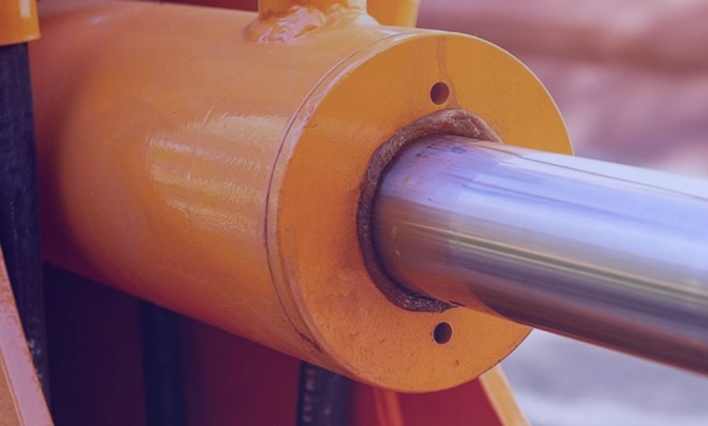
Hydraulic systems are widely used in the automobile industry, from braking systems in ordinary vehicles to earth moving systems in tractors. Because the pressure measuring or fluid transporting components in these systems are generally less than 10,000 psi, they may be tested and calibrated using the LP version.
Image Source: mensor
Higher Levels
Sometimes going large is necessary to achieve your aim. The CPC8000-H’s high pressure (HP) variant can create pressures ranging from 290 psi to 58,000 psi, however it is still regarded considerably safer than pneumatic systems. If you’re not in an area that demands high pressure systems, it’s difficult to see why anybody would need that much pressure, yet many applications in the aerospace, automobile, and oil refinery sectors do.
Pressures in diesel engine combustion tests can exceed 20,000 psi. Hydraulic calibrators are frequently employed in these applications to assess the accuracy of measuring equipment. To improve the refining process, the oil and gas sector relies on precise, high pressure gauge or transmitter readings. High pressure sensing equipment is frequently used in aerospace testing to safely test fuel systems before they are employed on multimillion dollar equipment. The use of very precise hydraulic controllers allows them to have confidence that their system can withstand excessive pressures prior to installation.
Call us to discuss your calibration, test or repair needs at: 713.944.3139.
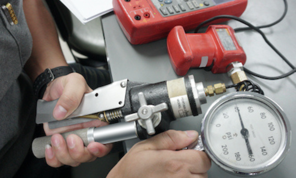
Pressure calibrations entail more than simply recording the pressure number and comparing it to a recognized standard. Because pressure measurements are affected by several factors such as temperature, local gravity, pressure medium characteristics, and local adjustments, it is critical to account for these external factors and corrections when performing high precision pressure calibrations.
There is a wide range of calibration software on the market that automatically adds these corrections to the recorded pressure values from the reference and DUT. However, understanding the sources of deviation and errors in the calibration setup can be aided by being aware of these adjustments.
Site specific adjustments
Specific modifications are made to the recorded value to account for characteristics that impact the pressure output in respect to the location of the site and the ambient environment. These modifications may include sea level adjustments, local gravity adjustments, and temperature variations in the surroundings.
Typically, sea level adjustments are done to account for variations in height and barometric pressure. To compensate for gravitational forces on masses, local gravity corrections are utilized. Temperature compensation is used to capture the correct reference device output as the ambient temperature changes.
Sea Level
This adjustment is critical for absolute ranges, especially barometric pressure ranges. Regardless of height, this adjustment gives a common barometric reference. Because all of the barometers are calibrated to sea level, this makes it easy for meteorologists to track weather fronts.
As the altitude of an absolute sensor increases, it approaches absolute zero. However, this might cause issues with a barometric range sensor because the reading will no longer be 14.5 psi when vented to atmosphere. The local barometric pressure may instead be 12.0 psi. This is not the case when a sea level adjustment is applied. The present barometric pressure in Denver, Colorado, for example, will be closer to 14.5 psi than 12.0 psi. This is due to the sea level adjustment done to the barometer sensor.
Local Gravity
A correction for local gravity is the final site-specific adjustment and perhaps the biggest contribution to inaccuracies, particularly in piston-gauge systems. Gravity is the acceleration that allows mass sets to exert force on the piston area, resulting in pressure. The gravity of the Earth varies over its whole surface, with the lowest gravity acceleration being around 9.7639 m/s2 and the maximum gravity acceleration being roughly 9.8337 m/s2.
The local gravity may be used during the pressure calculation for a piston gauge, and a gravity adjustment may not be required. Many industrial deadweight tests, on the other hand, are calibrated to standard gravity (9.80665 m/s2) and must be rectified.
Temperature
Temperature fluctuations are another source of mistake in pressure calibrations. While pressure transducers, such as the CPT9000 Premium Pressure Transducer, are temperature adjusted during production, not all transducers are. Manufacturers of such transducers establish the connection of the pressure output’s accuracy to temperature rise or drop through applicable temperature standards.
Temperature adjustment is especially necessary for reference standards requiring temperature monitoring, such as piston gauges. Piston-cylinder systems, regardless of composition (steel, tungsten carbide, etc.), must be temperature corrected during operation since all materials expand or contract in response to temperature changes based on their thermal expansion coefficient.
As the temperature of the piston cylinder rises, the piston-cylinder system expands, increasing the area and decreasing the pressure generated. As the temperature drops, the piston-cylinder system contracts, causing the area to shrink. As a result, the pressure created rises. This modification will be delivered immediately to the piston’s region.
Media related adjustments
Media-related changes may be irrelevant to regular users of pressure controllers or gauges. However, media-related changes are required for primary standards since they affect the desired target specification and associated uncertainty.
Air Buoyancy
Air buoyancy is one of the most critical modifications that must be made to piston-cylinder systems.
The pressure generated by the air surrounding us acts as a column of air. It also exerts an upward pull on things at the same time. If this modification is not made, the displayed value may be incorrect. Any mass, including the piston, will require what is known as an air buoyancy adjustment.
This adjustment is only required for gauge calibrations in which the reference is exposed to ambient air (atmospheric reference). It is insignificant for absolute since the ambient air is effectively eliminated by using vacuum as a reference.
Surface Tension
When using oil-lubricated piston-cylinder systems, the surface tension of the fluid must be overcome in order to “free” the piston. Essentially, depending on the diameter of the piston, this results in an extra “phantom” mass load. As the piston’s diameter rises, so does the effect.
This adjustment is more critical at lower pressures and becomes less relevant as pressure increases.
Device specific adjustments
Device-specific modifications, such as head height and distortion correction (piston-cylinders only), are required for precision devices where slight changes in measurement might contribute to inaccuracies that effect the calibration’s total uncertainty.
Distortion
A distortion adjustment is a comparable correction that must be performed to piston-cylinder systems. As the pressure on the piston-cylinder system grows, the piston area increases, forcing it to create less pressure.
As the pressure grows, the piston area expands, resulting in less pressure than intended. The distortion coefficient is normally supplied by the manufacturer, although it may also be measured experimentally.
Head Height
If the reference standard is a pressure controller, the only correction that may be required is a head height correction. This adjustment cancels out the discrepancies in height / placement of the sensing elements in the reference relative to the DUT. If the DUT is below the reference level, the value will be positive; if the DUT is above the reference level, the value will be negative. A head height correction must be determined regardless of the pressure medium and dependent on the precision and resolution of the DUT.
Mensor pressure controllers, such as the CPC6050, Modular Pressure Controller, allow the operator to enter a head height and the instrument will compute the corrective head height.
Conclusion
Being aware of and compensating for the elements that influence the output of your pressure calibration may make a substantial difference in the total uncertainty of a calibration. While some of these adjustments, such as local gravity and sea level, will remain constant between calibrations, others will change dramatically depending on the reference device, pressure range, and even the equipment under test.
Let Gulf Coast Manage Your Calibration Schedule.
Are you looking for calibration services, or is your equipment producing out-of-the-ordinary results? If so, you’ve come to the right place. Gulf Coast Calibration has over 40 years of expertise and has developed to become one of the Gulf Coast region finest weighing equipment and calibration firms. Our calibration services, which encompass equipment in a variety of sectors, are provided through our in-house laboratory or on-site at our clients’ facilities.
Call us to discuss your calibration, test or repair needs at: 713.944.3139.
When considering how to build or enhance a calibration program, there is a lot to consider. Especially when dealing with a wide range of pressure ranges – both high and low – when gas and liquid are employed in the process and as the calibration medium. The fundamental issue is always safety. The pressure range and media that are planned or present in your calibration scope are intimately connected to safety. Fortunately, there are several factors that impact the use of one media over another.
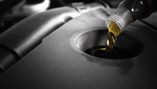
Hydraulic oil being poured into an instrument
What Pressure – What Media??
The distinction between high and low pressure is purely arbitrary. High pressure often refers to pressure ranges exceeding 10,000 psi for pressure calibration components, however this is a matter of opinion and the unique operating environment. Everything is dependent on the extent of the action. If your highest range is 3,000 psi, it is your “high pressure.”
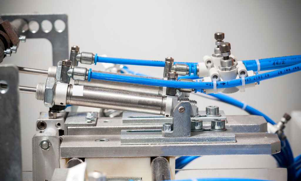
In general, pneumatic medium is utilized to calibrate the majority of pressure sensors with pressure ranges less than 1,500 psi. Some specialized applications need pneumatic media at pressures of up to 10,000 psi. As pressure rises, hydraulic fluids, most typically water or oil, become the dominating medium. It is safer to utilize hydraulic media at these higher pressure levels for the reasons explained below. The capacity to do pneumatic calibrations at pressures more than 10,000 psi exists, although it is an exception and is normally discouraged for safety concerns.
Safety
The amount of energy stored in a container filled with air or a non-volatile gas depends on the pressure and volume of the system. Because of its compressibility, pneumatic medium can store far more energy than hydraulic media. The greater the volume or pressure, the more energy is stored and potentially released in the event of a breach. A abrupt release of pressure into the environment in a high-energy pneumatic system is best defined as an explosion, and it may inflict significant harm to life and property.
Fortunately, most calibrating systems have modest volumes and hence reduced energy, but they can still inflict harm when in close proximity to a breach. The biggest worry in safety is the possibility of a high energy system containment failure. Because the volume of a typical calibration system is small, the major variable of interest is pressure. As a result, hydraulic media is often employed at pressures more than 10,000 psi. When using pneumatic media at pressures more than 10,000 psi, correctly rated fittings and tubing must be used to keep the gas contained inside the system.
Fittings
The standard industrial connectors used for connecting calibrating components containing both hydraulic and pneumatic media have a maximum pressure range of 10,000 to 15,000 psi. Fittings designed for higher pressure systems can also be utilized in low pressure systems. Elastomeric seal fittings must be compatible with the fluids utilized. Fittings developed specifically for greater pressure generally have a maximum pressure of at least 60,000 psi. Most of these are compatible with hydraulic or pneumatic fluids at their rated pressures; however, careful pressure and media selection is required.
Tubing
Depending on the wall thickness, pressure ratings for 1/4 inch OD (outside diameter) seamless stainless steel tube range from 4,000 to 10,300 psi. Fittings and tubing components often used in industrial applications or calibration labs to hold pressure and transmit fluids (both gas and liquid) have pressure ratings of up to and around 10,000 psi. Hardened stainless steel tubing can bear pressures of up to 60,000 pounds per square inch. These tube types are suitable for both gases and liquids.
Flexible nylon tubing with a working pressure rating of roughly 300 psi is often utilized in calibrating applications. Synthetic fiber reinforced flexible tubing with a value of roughly 5,800 psi is also employed. Flexible tubing is often used for pneumatic media, whereas stainless steel tubing is utilized for hydraulic media.
Compatibility
When a device is used in a process that contains hydraulic media, it is usually better to calibrate it using hydraulic fluid. If it is calibrated with air or nitrogen, it must be carefully cleaned to avoid contaminating the pressure calibrator. Alternatively, if a device under test is utilized with a gas and calibrated with a liquid, it must be cleaned before being returned to service to avoid process contamination. These factors must be considered before using a pneumatic or hydraulic medium as the calibration medium.
Pneumatic Media Types
In calibrating applications, pneumatic media are often clean, dry air or nitrogen. Other media, especially inert gasses, can be employed but are often more costly. Because of the significant danger of leakage, some inert gases, such as helium, may need to be avoided. Outside of specialist equipment and optimum calibration settings, flammable gases, such as oxygen, should be avoided, since they can induce spontaneous burning of residual oil at high pressures. The majority of other gases are rarely utilized in calibration.
Hydraulic Media Types
Hydraulic media can be deionized water or oil, depending on the equipment being tested and the calibrator used to generate the pressure. Many fluids can be utilized, but they must be compatible with the equipment under test and the calibrator. Distilled water, sebacate oil, HFE-7500, Shell Tellus-22, and other fluids are commonly used. Fluid recommendations should be provided by the calibration device’s manufacturer.
Conclusion
Many factors influence whether pneumatic or hydraulic media should be used in a calibrating application. Safety, both in terms of equipment and staff, is frequently the first priority. High-pressure pneumatic systems are more dangerous than high-pressure hydraulic systems. When calibrating devices that utilize a different medium, verified compatibility or rigorous cleaning instructions must be followed. To guarantee that all safety hazards are addressed, tubing, fittings, and seals must all be suitable with the medium being utilized.
Let Gulf Coast Manage Your Calibration Schedule.
Are you looking for calibration services, or is your equipment producing out-of-the-ordinary results? If so, you’ve come to the right place. Gulf Coast Calibration has over 40 years of expertise and has developed to become one of the Gulf Coast region finest weighing equipment and calibration firms. Our calibration services, which encompass equipment in a variety of sectors, are provided through our in-house laboratory or on-site at our clients’ facilities.
Call us to discuss your calibration, test or repair needs at: 713.944.3139.